The TPS (Throttle Position Sensor) on my 1985 Corvette bit the dust after 18 years. I purchased a new one from a local dealership and installed it. In the two years following its replacement, I noticed an erratic idle that got progressively worse. Like most people would do, I refused to believe the TPS was bad because it was "new" even though the car's computer was throwing Code 21's (TPS Signal Voltage High.)
However, when I checked the TPS voltage at idle it was not the .54 volts I expected and nowhere near the .54 volts that I had originally set it to about two years prior, but 2.5 volts.
I searched my GM Corvette service manual and discovered that they only specify an "on-car" diagnostic for the TPS. Needless to say their diagnostic showed the TPS to be bad.
After looking at the schematic for the TPS (below) I could see that it was just a variable potentiometer. GM did not include any specifications for the resistance values if you simply wanted to "ohm it out." Out of curiosity I measured the resistance between pins A & C and discovered that the circuit was completely open unless I placed some sideward pressure on the pins, then I would get a reading. Clearly I had an intermittent connection inside the TPS.
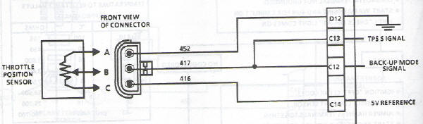
I then measured the resistance between pins B & C and saw that there was a measurable resistance that changed as the TPS actuator arm was moved. This was to be expected.
Without a good path to ground on pin A, the 5 volt reference could not be pulled to ground and so the TPS potentiometer could not return a variable voltage on the wiper contact B.
So, here's the pertinent info:
With a new TPS in hand (Part # 1711-1606) I've documented the values that you should see if you want to do a quick TPS check with an ohm meter:
| TPS Actuator Arm at rest: | Pins | Values (ohms) | ||||||
|---|---|---|---|---|---|---|---|---|
| A to C | = | 5.88k | ||||||
| A to B | = | 2.44k | ||||||
| C to B | = | 8.32k | ||||||
| Rotating the TPS Actuator Arm: | At Rest | Rotated | ||||||
| A to B | = | 2.44k | 8.26k | |||||
| C to B | = | 8.32k | 2.39k | |||||
Final Notes:
An observant reader might wonder how the ohm value across pins A & B or pins C & B can be greater than the ohm value across pins A & C? Well after opening up my old TPS I've discovered that it isn't quite as simple internally as the schematic diagram would lead you to believe. There's actually two wiper elements inside the TPS and two resistive elements. I'm not going to draw a diagram as it is beyond the scope of this article. Suffice it to say that the TPS works as shown in the schematic but is not constructed as shown in the schematic.
After installing the new TPS, several anomalies disappeared:
1) Random high 1,400 RPM idle
2) Random ECM Code 21's
3) Random loss of 4+3 overdrive
The random loss of the overdrive is a curiosity to me. I can only guess that the bad TPS was making the ECM think I was flooring the accelerator and causing the 4+3 overdrive to kick-out.
Because so much of what the ECM (Electronic Control Module) (computer) does is dependent upon a working Throttle Position Sensor I thought it would be good to provide a little more info to the Corvette hobbyist than what is found in the GM service manuals.
Also, this info applies only to 1985 models, in particular, mine. It may be applicable to later years, but I have no way of determining this.